Tutorial:
FDTD & GPU
Yee's algorithm
Sources
Materials
Boundary conditions
Near-to far field
Application notes
Application note: Reflection diffraction grating based on AFM data
In this example we will try to simulate reflection from metallic grating. In contrast to transmission grating example we will be using a realisitic geometry model based on grating topography measurements using atomic force microscope.
 |
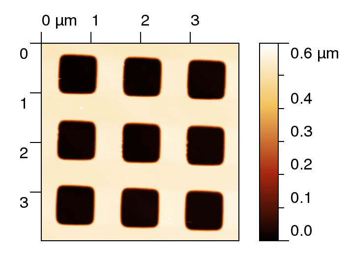
A typical image of diffraction grating topography is shown in the left figure (measured by atomic force microscopy). We can see several holes forming the grating and we want to use this data to create model of a infinite periodic grating. Using real topography data has many advantages if we want to model realistic samples. Of course we could pick only part of the grating containing single hole (like in transmission grating example), or use much more of holes (and all this could be reasonable, depending on what we want to model), this is just an example of how to use this particular data set. To help with establishing the parameter file and volume material and post-processing we have created a simple Gwyddion module (so we can easily pick the requested height field and easily show results), however both data preparation and postprocessing could be done using any other tool, none of specific Gwyddion algorithms was used. Note that the example was created using GSvit 1.2, some of its limitations may be overcome in later versions, making the simulation more straightforward. |
|
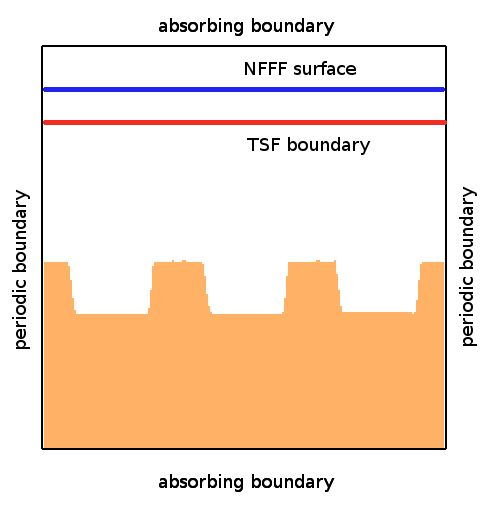
Image on the right shows a scheme of the computational volume used for the simulation (a cross-section). We use a parallelepiped of 230x230x200 voxels bounded by simple absorbing boundary conditions. A plane wave source is established using Total/Scattered field (TSF) approach, but only single plane is used to excite the plane wave (all the other faces are skipped). This is due to periodic boundary conditions that are applied, forming four internal computational domain walls parallel to light propagation direction. Only internal 200x200x200 voxels are therefore used for further computation as shown on the right image. A height field representing the grating is centered in the parallelepiped. Linear material is used to introduce height field, i.e. values of electric and magnetic properties are loaded for full volume (an alternative would be to load Gwyddion height field using vector material approach, or to construct totally synthetic vector data input based on primitive geometric entities). To evaluate far field scattering pattern, a periodic NFFF computational boundary is established, in contrast to transmission grating example it is now above grating (direction towards incoming wave). |
 |
Far field radiation pattern is again evaluated on a sphere (or its part) with prescribed radius like in transmission grating example.
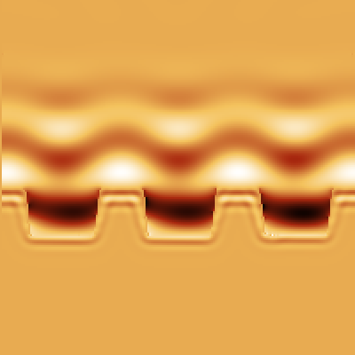
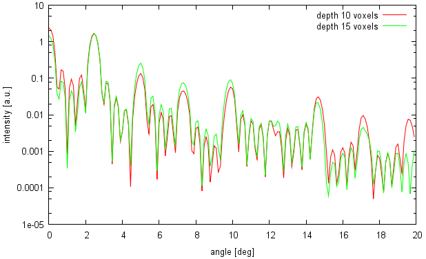
A typical snapshot from the simulation is shown in the following image (on the left). As a result we obtain a far field radiation pattern as shown in the right image (shown for two different grating depths).
 |  |
